
Tech Info –
Imaging Techniques
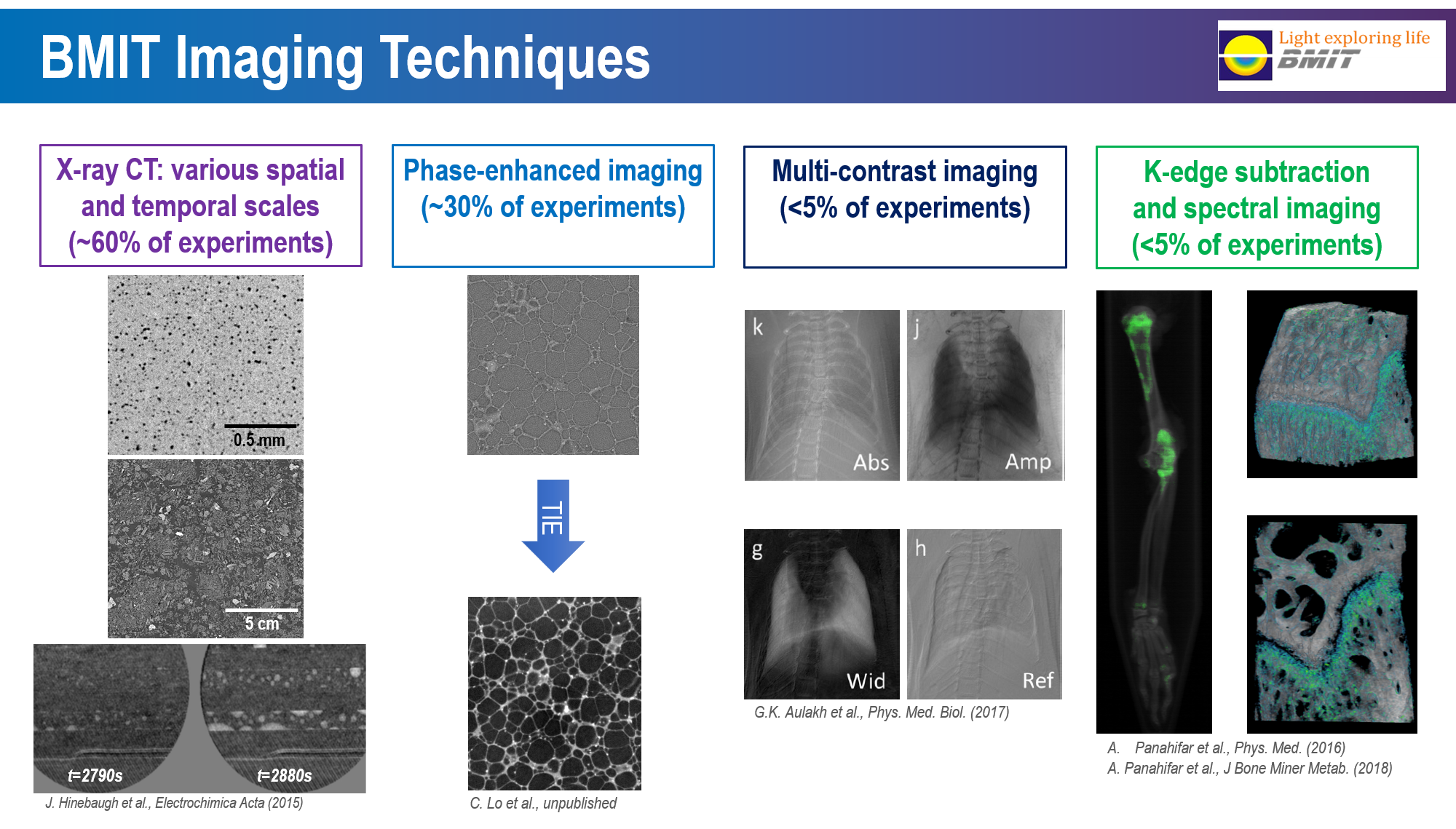
Absorption Contrast Imaging
X-ray absorption contrast imaging is the most common imaging technique, and is the technique used in industrial or hospital X-ray imaging, also called radiography. The contrast is driven by a combination of three factors: 1) Absorption differences; 2) Density differences; 3) Object thickness. Synchrotron based X-ray absorption contrast imaging uses a small spot size, high brightness, and a monochromatic beam to scan samples and can provide a high resolution composite image. Using a monochromatic source avoids the beam-hardening issues commonly found in conventional sources. High brightness can result in faster imaging for a comparable resolution.
Phase Contrast Imaging (Phase Sensitive Imaging)
X-ray phase-contrast imaging techniques make use of the refraction of X-rays by the sample in image formation. This provides considerable additional information in the image compared to imaging methods relying solely on X-ray absorption by the sample. Phase-contrast imaging highlights edges and internal boundaries of a sample and is thus complementary to absorption contrast, which is more sensitive to the bulk of the sample. Phase-contrast can also be used to image low-density materials, which do not absorb X-rays sufficiently to form a distinct absorption X-ray image. The following phase contrast imaging techniques are available at the BMIT.
- In-line Phase Contrast Imaging (Propagation Phase Contrast Imaging)
In-line phase-contrast imaging, which is also called phase-contrast radiography, is the most common technique and the easiest method to use. The synchrotron provides the spatially coherent source needed for this method. The setup is very similar to a typical radiograph with a source, a sample and a detector. The difference is that rather than placing the detector close to the sample it is located at some distance which gives rise to Fresnel fringes. This method is most sensitive to abrupt changes in the refractive index. This leads to an edge enhancement which increases the contrast of the edges of structures or material boundaries.
- Analyser-Based Imaging - Also called Diffraction Enhanced Imaging (DEI) / Multiple Image Radiography (MIR)
Analyser-based imaging is based on placing an analyser crystal between the sample and the detector. The crystal acts as an angular filter and only allows a small range of refracted and scattered X-rays to reach the detector. This allows for the measurement of an absorption image that is not blurred by scattered X-rays.
By tuning the analyser crystals refracted X-rays result in increased or decreased intensity in the image. Images are taken at two angles and then processed to obtain separate absorption and refraction images. Diffraction-enhanced imaging (DEI) is an analyzer crystal based X-ray imaging technique that has very high sensitivity to small changes in the refractive index. This makes it suitable for soft tissues such as in mammography or bone cartilage studies.
Multiple image radiography (MIR) is an extension of DEI to three or more images. Typically images are collected at 3 – 11 positions and then processed to yield three images depicting separately the effects of refraction, ultra-small angle scatter and attenuation by the object. All three images have good contrast, in part because they are virtually immune from degradation due to scatter.
Phase Contrast Comparison
| Analyzer | Propagation | |
|---|---|---|
| Requirements | ||
| Spatial coherence | Reasonable | High |
| Temporal coherence | High | Low |
| Capabilities | ||
| Full field | Difficult | Easy |
| Movies (fast radiography) | Hard | Easy |
| CT | Hard | Easy |
| Sensitivity | Excellent But unidirectional |
Good |
K-Edge Subtraction Imaging (KES) / Spectral KES
K-Edge Subtraction (KES) utilizes the discontinuity in the X-ray absorption across the absorption edge of the selected contrast element and creates a logarithmic subtraction image from two images acquired just above and below the K-edge energy of the contrast element. From the logarithmic subtraction of the two images, the visibility of structures, the visibility of structures containing the contrast element can be greatly enhanced and the signals to the other structures are practically suppressed.
Spectral KES is similar to conventional KES imaging. The spectral method, termed 'spectral-KES' employs a continuous spectrum encompassing an absorption edge of an element within the object. The spectrum is prepared by a bent Laue monochromator with appropriate focal and energy dispersive properties. The monochromator focuses the spectral beam at the object location, which then diverges onto an area detector such that one dimension in the detector is an energy axis. A least-squares method is used to interpret the transmitted spectral data with fits to either measured and/or calculated absorption of the contrast and matrix material-water. The spectral-KES system is very simple to implement and is comprised of a bent Laue monochromator, a stage for sample manipulation for projection and computed tomography imaging, and a pixelated area detector.
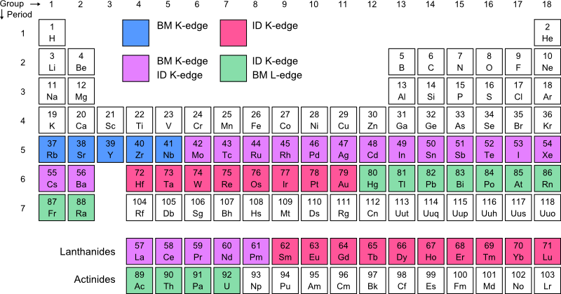
This periodic table show the absorbtion edges that can be reached at the beamlines. In this table BM indicates the bend magnet source (05B1-1) and ID indicates the insertion device (O5ID-2).
Computed Tomography (CT)
Computed tomography (CT) makes use of computer-processed combinations of many X-ray projections taken from different angles of a sample to produce cross-sectional (tomographic) images of specific areas of the sample, which provides three-dimensional (3D) structural information of the scanned sample. CT is available at BMIT and can combine with any imaging techniques at BMIT, such as absorption-CT, phase-contrast-CT, DEI-CT, Spectral KES-CT.